
Customer Supplied Materials Guideline
These international guidelines developed by the Association Connecting Electronics Industry or IPC have helped standardize the assembly and production of electronic equipment and assemblies. Following these guidelines will allow for a smooth and accurate quoting and manufacturing process.
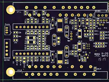
Customer Supplied Bare PCB’s
Minimum single PCB/array size for equipment use = 3.00” x 3.00” which can include rails
- Maximum single PCB/array size for equipment use = 17.00” x 20.00” which includes rails.
- Minimum of two fiducials on opposite corners of the PCB on both sides are required for accurate solder and component alignment and placement. Use 0.040” round apertures with some soldermask clearance.
- Fiducials must be at least of 0.250” from rail edges to prevent obstruction from machine clamps
- Add at least 0.250” rail on all sides of PCB to accommodate machine handling if possible or where it makes sense, as sometimes only putting rails on two sides would be better due to components overhanging.
- Minimum of two fiducials on opposite corners on the rails (if used) are required for accurate solder and component alignment and placement. Use 0.040” round dots with some soldermask clearance. These fiducials should be in addition to the PCB fiducials.
- Fiducials must be at least of 0.250” from rail edges to prevent obstruction from machine clamps.
- Fiducials should not be on all four corners of the PCB as this can lead to misplaced parts if the PCB is placed into the machine incorrectly.
- Typically, the other two open corners may have mounting holes added but is not required.
- If PCB is over 0.093” thick, putting rails on the PCB might not be advisable. Please make sure if your PCB does not have rails that there are fiducials on the PCB.
- Rails with V-Scoring
- V-Scores are applied on both top and bottom sides of the PCB along the PCB edge between the PCB itself and the added rails. It is a “v” shaped groove leaving approximately 1/3 of the PCB thickness with a web of the remaining material to support the PCB and stay attached.
- V-Scores are made with a V shaped bit that typically has either a 300 or 450 angle. The smaller the angle the smaller the cut into the actual PCB will be.
- Depending on PCB thickness, the webbing left after v-scoring is typically 0.016” to 0.012”.
- Components or other features should not be too close to the PCB edge wherever possible or damage may occur during the depaneling process.
- Rails with Tabs/Mousebites and Routing
- Tabs or mousebites with routing might be necessary when v-scoring is not an option but Pro-Active would prefer to have v-scores instead of tabs/mousebites.
- Typically, this is needed for circular or Flex PCB’s or very thin PCB’s where v-scoring leaves the PCB rails too flimsy to stay attached.
- The location of the tabs or mousebites should be carefully located if they might interfere with assembly or placement into higher level assembly enclosures where size and shape may be critical.
- Tabs or mousebites with routing might be necessary when v-scoring is not an option but Pro-Active would prefer to have v-scores instead of tabs/mousebites.
- Add at least 0.250” spacing rails between PCB’s in array if components overhang.
- Depending on the type of component and how the component overhangs, routing into the rails may be necessary especially with SMT USB connectors that have a lip that hangs over the edge of the PCB itself once placed.
- Minimum of two fiducials on opposite corners on the rails (if used) are required for accurate solder and component alignment and placement. Use 0.040” round dots with some soldermask clearance. These fiducials should be in addition to the PCB fiducials.
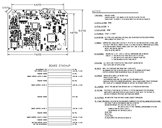
Bare PCB File Requirements
- The RS-274X standard is preferred for Gerber files as this file format automatically assigns the
D-Code aperture settings and includes other helpful meta-information.
- Include NC Drill Files, Drill Chart, and PCB Specs.
- Drill Chart and PCB Specs can be a PDF if not included in the actual gerber files.
- Include PDF of Schematics.
- Include at least one of the following files for equipment programming and documentation:
- IPC-2581 (Preferred)
- ODB++
ASCII
Customer supplied component requirements
- The customer is responsible for providing RoHS compliant Bill of Materials if the assembly requires it. If required, Pro-Active Engineering will build assemblies in accordance to RoHS compliant processes.
- It is recommended that the customer send extra parts due to leaders and/or attrition during the PCB assembly process. Pro-Active Engineering does not experience much loss, but to be safe Pro-Active Engineering would appreciate having a small amount of overages to avoid any delays in assembly.
- Lead time may be impacted if the proper leader and/or attrition is not supplied. If you have expensive components or a minimum quantity of any component on hand, please contact your sales representative for details.
- Parts that are properly shipped in anti-static carriers or in moisture sensitive packaging will be treated with care while being inventoried, placed, and resealed. Any unused Customer supplied parts are returned with your assembly.
- Component Packaging Requirements
- Each component shall be individually packaged, labeled with the BOM line item number, customer part number and/or manufacturers’ part number.
- The following are acceptable packages of consignment / customer supplied components:
- SMT Reels
- Cut Tape
- Thru-Hole bulk or tape
- Tubes / Trays
- Digi-Key Reels
- SMT components, not supplied on reels, are required to be on one continuous strip of tape.
Component Overage Guidelines
Pro-Active Engineering requires overage of all parts for machine setup and run scrap and encourages all parts to be provided on one continuous strip of tape. Prior to ordering parts for an assembly, contact Pro-Active for the appropriate quantity needed for each line item. Pro-Active will forward a Manifest for the required part quantities when a Purchase Order for the assembly is received.
Please contact your Sales Representative or Account Specialist if the requirements stated above cannot be met or if there are any questions regarding the requirements.
PCB Fabrication Specifications
To best meet the needs of each individual customer, we offer a wide range of options for PCB Fabrication.
24-Hour Turn-Key Quotes
Why Pro-Active Engineering Stands Out
We are a full-service Electronics Manufacturing Service (EMS) provider. We are a small business that gets things done. Our roots are in electrical engineering and we provide our customers with the flexibility that large companies lose track of. Our ingenuity and grit have led to the mastery of complex boards designs and assembly requirements.


Why Speed Shop?
Ready, Set, Go!
We Will Meet Your Time Requirements
Our dedicated team of experts will guide you through the process and let you know upfront if we can deliver in your time frame. Not every job qualifies for quick-turn assembly, so let us review your requirements today and align you with the right solution today.

24 Hour Turn-Key Labor Only Jobs

BOM Protocol

We Ask the Right Questions

What Our Customers Are Saying
“I value the customer service Pro-Active Engineering was able to provide, getting us through our challenges”.
Rich M.
"We were referred to Pro-Active by another company as a world-class organization that provides quality products, excellent service, and competitive pricing."
Stacy J.
"Their willingness to 'get involved' with my project. Taking an interest, and truly understanding not just what I want designed/built, but why, and offering up insights that I may not have considered."
Dave W.
Memberships
emphasizing our commitment to continuous improvement


